The Deckhand newsletter · Issue 1 · Energy Street
Tank sloshing CFD study with open source software OpenFOAM
The Deckhand Chronicles is AceEngineer's newsletter. We help build AI into everyday engineering work.
Energy Street · Tank sloshing. Energy Street covers offshore engineering.
The closed-form formula for a tank's first sloshing frequency holds at small roll: our two-dimensional OpenFOAM model matches it within 0.30 % at four fill levels. At 8° roll, the resonance at 30 % and 70 % fill sits about 11 to 13 % or more below the formula. An anti-roll tank tuned from the formula alone needs a check at the vessel's own roll angle and roll axis.
Version 1.2, prepared 12 Nov 2026, from issue 1 of 27 Oct 2026. Full study: https://vamseeachanta.github.io/digitalmodel/cfd/sloshing-cfd-study.html
In this article:
- The formula and the CFD agree at small roll
- The resonance moves with roll angle and roll axis
- Tank damping has an optimum
- Run time on one workstation
The formula and the CFD agree at small roll
Sloshing matters in tanks on floating vessels. Near resonance, the liquid runs up the tank walls and strikes them. A partly filled tank tuned near a vessel's roll period can also act as an anti-roll damper. Both uses start from the tank's first sloshing frequency, the frequency at which the liquid swings most easily from wall to wall. This article gives that frequency from a closed-form formula and from open-source computational fluid dynamics (CFD). It shows how far the resonance moves at larger roll angles, and it names two checks, the roll angle and the roll axis, to apply to a sloshing study of your own tanks.
The study ran two-dimensional cases in OpenFOAM v2312 (December 2023; interFoam, volume of fluid). The benchmark tank is rectangular, 1 m long and 1 m high. In each free-decay run, a small first-mode wave rings down in the still tank, and its frequency is read from the record. Fill is the still-water depth as a share of the tank height. The analysis results for the two-dimensional tank case are compared to the available public literature. At fills of 15, 30, 50 and 70 %, the largest difference from linear theory is 0.30 %, at 30 % fill, where CFD is below theory. Refining the mesh from 1,600 to 25,600 cells moves that difference only from 0.326 % to 0.296 %. It comes mainly from the finite height of the starting wave, not from the mesh.
The resonance moves with roll angle and roll axis
Forced-roll runs drive a 0.9 m tank at 1 to 8° roll over a range of periods. They find the resonance from the phase of the tank's response (Bäuerlein and Avila 2021). At 30 % and 70 % fill, the resonant frequency falls as roll grows: about 1 to 4 % below the formula at 2°, and about 11 to 13 % below at 8°. These shifts come from runs of six roll cycles, which the study reads as lower bounds: a 12-cycle run gives a larger shift. At 15 % fill the resonance sits above the formula instead: 7.5 % above at 1°, and 1.2 % above at 8°, which is within the sweep's resolution. There the water crosses the tank as a breaking bore and runs up the wall to about three times its still depth at 8°.
Where the roll axis sits below the tank, for example for a tank high in the hull, the tank is also pushed sideways as it rolls (Kapsenberg and Carette 2023). At 70 % fill and 4° roll, rolling the tank about its own floor puts the resonance about 10 % below the formula, in a 12-cycle run; the 6-cycle point for 70 % fill and 4° in the chart below reads 8 %. With the axis half a tank length below the floor, the resonance sits about 16 % below; with the axis one tank length below, about 20 % below. The study quotes these shifts to the nearest percent. Peak wall run-up is about 15 % higher with the axis below the floor.
Tank damping has an optimum
The forced-roll runs at 4° also give each fill's equivalent damping ratio: 0.095 at 30 % fill, 0.18 at 50 % and 0.305 at 70 %. These feed a screening step with the classic tuned-absorber equations used for anti-roll tanks (Moaleji and Greig 2007), at a tank-to-vessel mass ratio of 0.05, with perfect tuning and no hull damping. The best damping ratio is then 0.13. At 30 % fill the tank is under-damped and splits the vessel's roll response into two peaks. At 70 % fill it is over-damped and the peak grows again. The 50 % fill gives the lowest roll peak of the three.
Run time on one workstation
Each case runs on one core. A batch of 48 forced-roll cases ran 14 at a time on one 32-core workstation in 34.7 min, against an estimated 247 to 336 min one at a time.
Read the full study: https://vamseeachanta.github.io/digitalmodel/cfd/sloshing-cfd-study.html
Charts and data
The first chart compares the CFD frequencies with linear theory. Its x-axis, labelled "fill / slenderness ratio h / L", is the fill depth h over the tank length L. The benchmark tank is square, so h/L equals the fill.
The second chart shows how far the resonance moves as roll grows, at three fills.
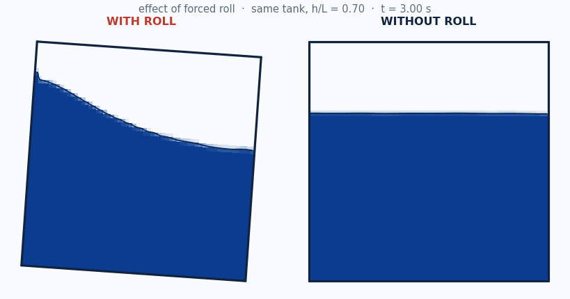
The animation shows one tank at 70 % fill, with forced roll on the left and none on the right.
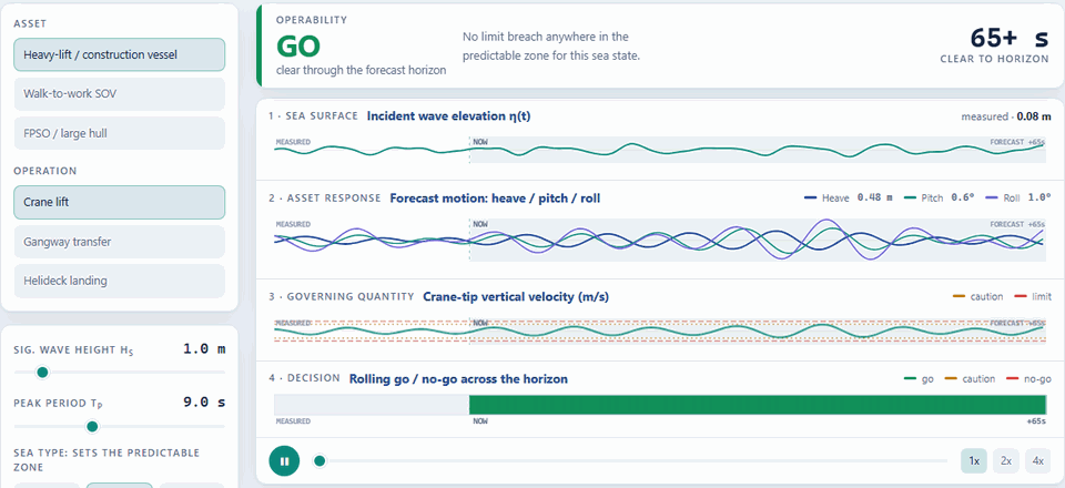
The motion-forecast demo runs in a browser. It forecasts vessel motion 65 s ahead on a simulated sea state and gives an illustrative go, caution, hold or no-go call; useful calls need live motion-sensor input. The animation steps the significant wave height from 1.0 to 4.0 m. Try the demo: https://vamseeachanta.github.io/digitalmodel/hydro/short-horizon-motion-forecast.html
To try it out or adapt the analysis, see reusable prompt.
If you have run your own analysis, see a way to improve this one, or have an idea for a future issue, write to support@aceengineer.com. We read every reply and credit the ideas we use and provide results we obtained.
Prepared: Analyst Deckhand · Checked: Editor Deckhand · Approved: Vamsee Achanta (12 Nov 2026). Deckhand roles are AI assistants on the AceEngineer team: they ran the analysis and prepared and checked this edition. Version 1.2, prepared 12 Nov 2026.
References
Project references
- AceEngineer, Tank sloshing CFD study with OpenFOAM, study page. https://vamseeachanta.github.io/digitalmodel/cfd/sloshing-cfd-study.html
- AceEngineer, The Deckhand Chronicles: Energy Street, Issue 1, 27 Oct 2026. https://www.aceengineer.com/newsletter/issue-001-energy-street/
External references
- Bäuerlein, B. and Avila, K. (2021), Phase lag predicts nonlinear response maxima in liquid-sloshing experiments. Journal of Fluid Mechanics 925, A22.
- Kapsenberg, G. and Carette, N. (2023), A consistent method to design and evaluate the performance of anti-roll tanks for ships. Ship Technology Research 70(2), 117-145 (online 21 Sep 2022). DOI 10.1080/09377255.2022.2117496.
- Moaleji, R. and Greig, A.R. (2007), On the development of ship anti-roll tanks. Ocean Engineering 34(1), 103-121.
Web references
- OpenFOAM v2312 (December 2023), OpenCFD Ltd, GPL v3 licence. https://www.openfoam.com/
Appendix A Reusable prompts
This prompt lets your team, or any assistant, recompute the theory side of our sloshing benchmark, compare it with our published CFD values, and read the resonance shifts at 8° roll from our archived data. With OpenFOAM, it also reruns a CFD case. To have a study of your own tanks done for you instead, see below.
What you need to run this
- Data required: None to reproduce the benchmark;
- Data required to adapt: tank length, fill depth and shape, your vessel's roll period, the roll angle of interest and the roll axis height.
- Paid or behind an account: nothing. OpenFOAM is free, open-source software.
- Changes over time: nothing. The CFD outputs are archived at a fixed commit.
Reproduce the published result
Give this prompt to your assistant:
Using the study at
https://vamseeachanta.github.io/digitalmodel/cfd/sloshing-cfd-study.html
and our public code repository https://github.com/vamseeachanta/digitalmodel
at commit 705857af62385a4567c96be99a129cdff3051a52 (MIT licence),
with Python 3.11:
1. Recompute the theory side and compare with our published CFD values.
   For a two-dimensional rectangular tank of length L and fill depth h,
   linear theory gives the first-mode frequency as
   Omega1 = omega1 * sqrt(L / g) = sqrt(pi * tanh(pi * h / L)).
   Compute it at h/L = 0.15, 0.30, 0.50 and 0.70. Compare it with the
   published CFD values 1.1779, 1.5164, 1.6974 and 1.7508, archived in
   docs/api/structural/sloshing-cfd-benchmark.json at that commit.
   Report each difference in %, signed: (CFD - theory) / theory.
   Check: theory 1.1746, 1.5210, 1.6974 and 1.7508; differences +0.28 %,
   -0.30 %, 0.00 % and 0.00 % (CFD is below theory at h/L = 0.30).
2. Read docs/api/structural/sloshing-backbone.json at that commit.
   Report detuning_pct at 8 deg roll for h/L = 0.30 and 0.70.
   Check: -10.81 % and -13.25 %.
3. Only if I have OpenFOAM v2312 on Linux, rerun the free-decay cases
   (about 10 min per case) at that commit:
     git clone --filter=blob:none https://github.com/vamseeachanta/digitalmodel
     cd digitalmodel
     git checkout 705857af62385a4567c96be99a129cdff3051a52
     source /usr/lib/openfoam/openfoam2312/etc/bashrc
     uv venv --python 3.11
     uv pip install --no-sources -e .
     .venv/bin/python scripts/cfd/run_sloshing_benchmark.py free-decay --work-dir ./sloshing-work
   The run rewrites docs/api/structural/sloshing-cfd-benchmark.json, so
   compare its new values with the step 1 check values above, not with the
   file itself.
Adapt it to your project
Before you start, ask me for: my tank length, fill depth and shape; my
vessel's roll period; the roll angle of interest; the roll axis height
below the tank floor.
These checks still apply when my result differs: the closed form holds for
a rectangular tank at small amplitude; the four published cases still
reproduce; any resonance is reported with the roll angle and roll axis
used.
Public data set: the archived OpenFOAM v2312 outputs, sloshing-cfd-benchmark.json, sloshing-backbone.json and sloshing-shallow-refine.json, at commit 705857af of our public code repositories (MIT licence, fixed). Code: our public code repositories, https://github.com/vamseeachanta/digitalmodel (MIT licence).
To have a study of your own tanks done for you, write to support@aceengineer.com.
Questions: support@aceengineer.com · AceEngineer · © 2026 AceEngineer · 11511 Piping Rock Dr., Houston, TX 77077
Deckhand: Make Engineering Enjoyable Again